
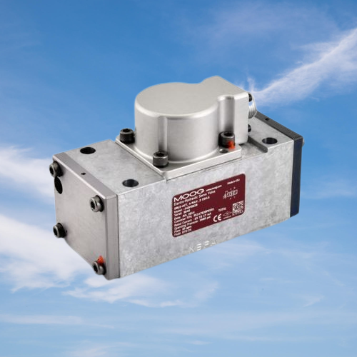
Deskripsi
Servo Valve
- Series : 743 and 744
- Model : 743P001
- Brand : MOOG Inc.
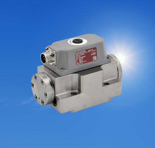
The MOOG 743 and 744 series valves feature a simple and robust design, ensuring reliable and long-lasting operation. The MOOG 743 series industrial servo valve consists of a polarized electric torque motor and a two-stage hydraulic power amplifier. The motor armature extends into the air gap of the flux loop and is fixed there by a flexible tube. The flexible tube acts as a seal between the valve’s electromagnetic and hydraulic components. Two motor coils surround the armature, located on either side of the flexible tube. A baffle of the hydraulic amplifier is rigidly connected to the midpoint of the armature, extending through the flexible tube between two nozzles, forming two variable orifices between the nozzle heads and the baffle. The pressure controlled by the baffle and the variable orifices of the nozzles is delivered to the end region of the secondary valve spool. The secondary stage uses a conventional four-way valve spool design; under fixed valve pressure drop conditions, the valve output flow is proportional to the spool’s deviation from zero. A cantilevered feedback spring is fixed to the baffle and engages with the spool’s groove. Valve spool displacement causes the feedback spring to deflect, thus exerting a force on the moving iron/baffle assembly. The input signal induces a magnetic charge in the moving iron core, causing the core and baffle to deflect. This component pivots around the flexible tube, increasing the diameter of one nozzle orifice while decreasing the diameter of the other. This action creates a pressure difference across the valve core, inducing valve core displacement. This displacement transmits torque through the feedback line, acting in the opposite direction to the original input signal torque. The valve core continues to move until the force of the feedback line and the force of the input signal reach equilibrium.
Performance characteristics:
Two-stage flow control mechanical feedback valve
Nozzle-type pilot valve achieves high resolution and low hysteresis characteristics
High valve core driving force and robust design ensure long service life.
An intrinsically safe version is available for applications requiring the use of certified products in potentially hazardous environments.
Replaceable pilot valve stage filter on site
The design complies with all requirements of General Electric Code 351A7620.
Optional features and accessories:
Intrinsically safe, magnetic zero-point adjustment, ventilated motor cover, reverse polarity protection
Optional three-coil pilot valve configuration enhances coil fault protection capabilities.
Optional fault protection mechanisms ensure reliable and controllable actuator movement when signals are lost.
Electrical connectors
Mounting bolts
Replace the filter kit
Technical Parameters:
| Origin | USA |
| Hydraulic parameters | |
| pressure difference | 70 bar; 1,000 psi |
| Rated flow rate | 75 to 95 l/min; 20 to 25 gpm |
| Standard configuration | 95 l/min; 25 gpm |
| Max work pressure | 210 bar; 3,000 psi |
| Performance parameters | |
| Response characteristics at a system pressure of 3,000 psi | |
| Step response | 25 ms |
| Frequency response with 90° phase lag | 45 Hz |
| Operating temperature | -40 to +185℉; -40 to +85℃ |
| Max fluid viscosity | 6,000 SUS |
| Electrical parameters | |
| Rated signal single coil | 8 to 60mA |
| Standard configuration | 16, 48 mA |
| General Specifications-016 | |
| Base O-ring dimensions (cross-section × inner diameter) | 0.070 × 0.614 inches; 1.78 × 15.59 mm |
| General Specifications-011 | |
| Auxiliary pilot pressure port O-ring dimensions (cross-section × inner diameter) | 0.070 × 0.301 inches; 1.78 × 7.65 mm |
| weight | 1.54 kg; 3.4 lbs |
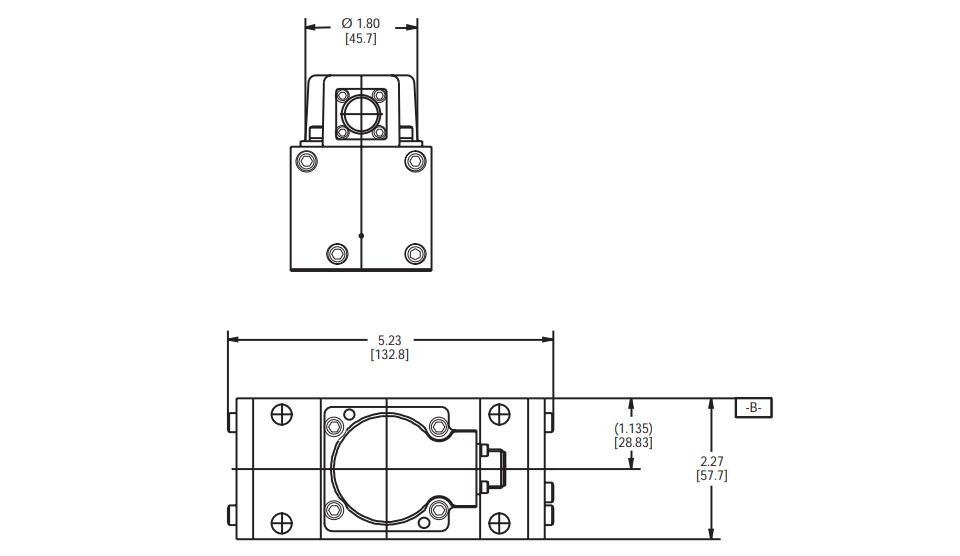
Product Dimensions:
Ulasan
Belum ada ulasan.