

Deskripsi
Emergency Stop Interlock Switch
1. Product Overview :
Emergency stop interlocking switch (hereinafter referred to as emergency stop switch) is suitable for use in hazardous locations with explosive gas mixtures and workplaces such as open-pit coal mines and coal preparation plants, as an emergency stop signal detection device for the integrated protection and control device of mining belt conveyors.
2. Main Technical Features
2.1 Explosion-proof type: Intrinsically safe for mining, explosion-proof mark: ExibI;
2.3 Contact capacity: 30V/10A;
2.4 Contact resistance at the contact points ≤ 0.1Ω, ≤ 0.2Ω after vibration and impact;
2.5 Action force: 60N±10N; Reset force: 60N±10N;
2.6 Operational Performance: When an outward force is applied to the drive ring on either side of the emergency stop switch,
The contact state inside the emergency stop switch should be reversed and self-locking; when an outward force is applied to the corresponding reset pull ring, the contact state inside the emergency stop switch should be restored.
2.7 External dimensions: 165mm × 90mm × 160mm;
Weight: 2 kg.
3. Environmental conditions:
3.1 Normal working conditions
a) Ambient temperature: -5℃~+40℃;
b) Average relative humidity: not greater than 95% (+25℃);
c) Atmospheric pressure: 80 kPa~106 kPa;
d) In situations where there is no significant vibration or impact;
e) In situations where there are explosive mixtures such as coal dust and methane, but no corrosive gases that could damage insulation;
f) Pollution level: Level 3
g) Installation category: Class III.
3.2 Harsh storage and transportation conditions
High temperature: 60℃
Low temperature: -40℃
Average relative humidity: 95% (25℃).
Vibration: 50 m/s²
Impact: 500 m/s².
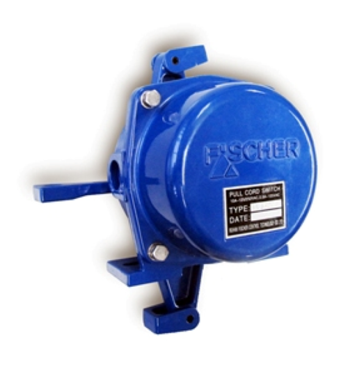
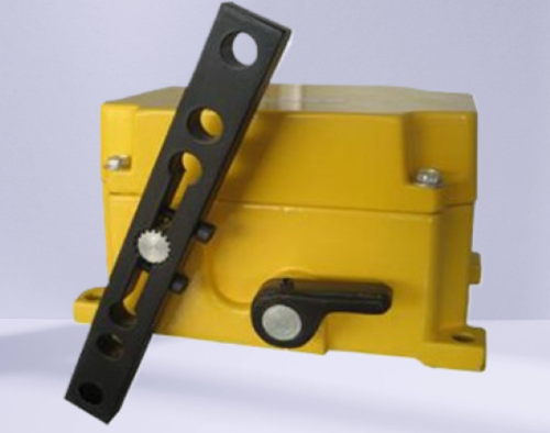
4. Structural Overview:
An emergency stop switch consists of a housing, a limit switch, an emergency stop pull ring, a reset pull ring, and terminals.
5. Working Principle:
When a force of 60N±10N is applied outward to the emergency stop pull ring on either side of the emergency stop switch and displacement occurs, the limit switch inside the emergency stop switch will activate, the contact state will flip, and it will self-lock; when a force of 60N±10N is applied outward to the corresponding reset pull ring, the limit switch inside the emergency stop switch will activate again, and the contact state will be restored.
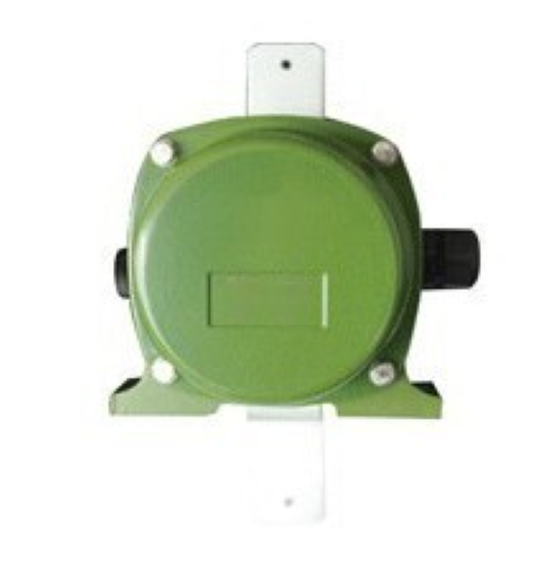
6. Installation:
Install the emergency stop switch on the brackets on both sides of the belt conveyor, and connect the emergency stop rings of the emergency stop switch one by one with the pull rope. Open the emergency stop switch junction box, and connect J (emergency stop signal) and O (power ground) to the corresponding terminals in the main unit of the belt conveyor integrated protection and control device with the cable.
6.2 Debugging
When a force of 60N±10N is applied outward to the emergency stop pull ring on either side of the emergency stop switch and displacement occurs, the limit switch inside the emergency stop switch will activate, the contact state will flip, and it will self-lock; when a force of 60N±10N is applied outward to the corresponding reset pull ring, the limit switch inside the emergency stop switch will activate again, and the contact state will be restored.
Ulasan
Belum ada ulasan.