

Deskripsi
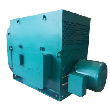
Induced Draft Fan Set C/W Motor YKK3551-4
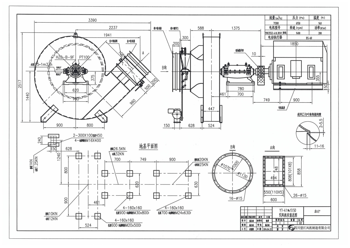
INCLUDE ACCESSORIES : Imported MUFFLER, Electric Actuator, Single Channel Temperature Measurement, Soft Connection at Inlet And Outlet, Motor Base (Including Protective Cover), Local Junction Box Inlet and Outlet Adjusment Door.
Overview :
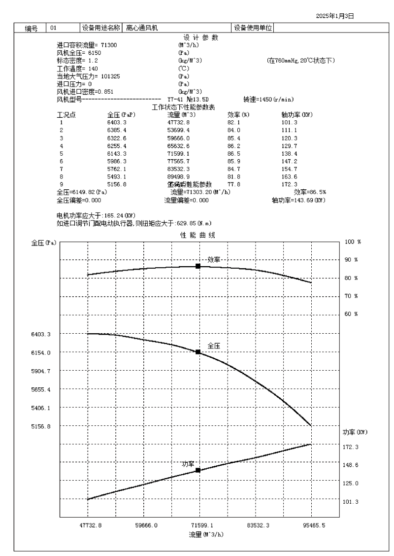
The main features of G/Y7-41 industrial boiler induced draft fan are: high fan efficiency, high total pressure, low noise, flat performance curve, wide economic use area, and backward plate blades. The fan has a total pressure internal efficiency of 86.5% at the .. operating point, and the noise index (specific A sound level) LS=11.5 decibels. These two indicators are at the .. level compared with various industrial boiler induced draft fans currently available in China. If this fan reaches the same flow and pressure as other models of fans, the fan main shaft speed can be greatly reduced (generally reduced by 200 to 800 rpm), so that the fan noise is significantly reduced and the operation is stable and reliable.
The medium conveyed by the ventilator is air, and the temperature shall not exceed 80℃. The medium conveyed by the induced draft fan is flue gas. Under the same flow rate, the pressure of this induced draft fan can be increased by more than 30% compared with the original Y5-47 boiler induced draft fan . Therefore, it is particularly suitable for 1 to 20T/h industrial boilers with spiral pipes and multi-tube dust collectors .
Type :
- Both the ventilator and the induced draft fan are made into single suction: the ventilator hasten models, including No.4.5 , 5.6 , 7.1 , 8 , 9 , 12.5 , 14 , 16 , 18 , and 20 ; the induced draft fan has twelve models, including No. 4.5 , 5.6 , 7.1 , 9 , 10 , 11 , 11.2 , 12.5 , 14 , 16 , 18 , and 20 .
- Both induced draft and induced draft fans can be made into left-hand or right-hand rotating fans. When looking at the fan from one end of the transmission unit, if the impeller rotates clockwise, it is called right-hand rotation, represented by “right”. If it rotates counterclockwise, it is called left-hand rotation, represented by “left”.
- The air outlet position of the fan is indicated by the air outlet angle of the housing. Both “left” and “right” can be set to three angles: 0°, 90°, and180°.
- The fan transmission modes areA , C and D.
The fan consists of an impeller, a casing, an air inlet, a transmission group and an adjusting door.
- Impeller: It is made of backward inclined blades welded between the arc-conical wheel cover and the flat wheel disc. After dynamic and static balance and overspeed operation tests, it runs smoothly and has a long service life.
- Casing: Steel plates are welded into a spiral casing. The left and right turns are universal for №8 and above.
- Transmission group – The main shaft is made of steel and adopts ball bearings. The No. 4.5~7.1C transmission adopts an integral two-open bearing seat, uses No. 2 calcium-sodium based grease and the fan blades are self-cooled, and the structure is simple.
- Air Inlet – The convergent-divergent air inlet is made into an integral structure and fixed to the inlet side of the casing with bolts.
- Adjustment door – adjust the fan flow. Fans No. 9 and below use a 3-blade louver structure, which is flexible to close and simple in structure. Fan No. 10 uses an 11-blade petal-shaped structure, which is axially installed in front of the air inlet. The adjustment range is from 90° (fully closed) to0° (fully open). The position of the adjustment door lever is from the air inlet direction. For a right-rotating fan, the lever turns counterclockwise from fully closed to fully open, and for a left-rotating fan, the lever turns clockwise from fully closed to fully open.
In order to ensure the normal operation of all parts of the regulating door, lubrication is necessary. Since the temperature of the induced draft fan gas is relatively high, the lubricating grease is high-temperature ( 260 °C) slush grease, which can still provide lubrication during high-temperature operation.
The bearing box of this fan is a water-cooled bearing box. The lubricating oil is No. 30 machine oil. The amount of oil added is in accordance with the requirements of the oil level mark. During installation, a water pipe must be installed. The water consumption varies with the temperature and is generally considered to be 0.5-1m3 /h .


Ulasan
Belum ada ulasan.