
Deskripsi
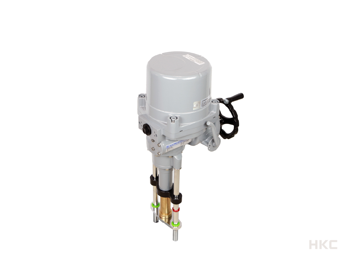
HL Series Electric Linear Actuator
MFR : HKC.Co.,Ltd.
• The HL Series, electric linear actuator, is designed for linear valve applications such as globe valve.
• Precise modulating control (300:1 at maximum stroke) as an option.
• Flameproof (Ex db IIB T4) and dust ignition proof (Ex tb IIIC T135°C) enclosures as an option
• Communication (PROFIBUS, MODBUS) options
Material
• Aluminium alloy
Enclosure
• Standard: weatherproof IP67
• Flameproof: Ex db IIB T4
• Dust ignition proof: Ex tb IIIC T135°C
• Flameproof: Ex db IIB T4
• Dust ignition proof: Ex tb IIIC T135°C
Certificates & approvals
• IECEx (Ex db IIB T4 Gb, Ex tb IIIC T135°C Db)
• ATEX (II 2G Ex db IIB T4 Gb, II 2D Ex tb IIIC T135°C Db)
• KCs (Ex d IIB T4 IP67)
• EAC (1 Ex db IIB T4 Gb X)
• CCC (Ex d IIB T4 Gb, Ex tD A21 IP6X T135°C)
• ATEX (II 2G Ex db IIB T4 Gb, II 2D Ex tb IIIC T135°C Db)
• KCs (Ex d IIB T4 IP67)
• EAC (1 Ex db IIB T4 Gb X)
• CCC (Ex d IIB T4 Gb, Ex tD A21 IP6X T135°C)
Output force
• 5,000 to 25,000 N
Power
• 110/220 V ac 1ph, 50/60 Hz, ±10%
• 220/380/440/480 V ac 3ph, 50/60 Hz, ±10%
• 24 V dc
• 24 V ac/dc
• 220/380/440/480 V ac 3ph, 50/60 Hz, ±10%
• 24 V dc
• 24 V ac/dc
Duty cycle
• S2(on-off): 30 mins (room temp., average load of 50% of max. torque)
• S4(modulating): 40~70% 800~1200 starts/hour (room temp., average load of 50% of max. torque)
• S4(modulating): 40~70% 800~1200 starts/hour (room temp., average load of 50% of max. torque)
Ambient temperature
• Standard: -20 to +70 °C
• Flameproof/dust ignition proof: -20 to +60 °C
• Low temperature: -60 to +60 °C
• Flameproof/dust ignition proof: -20 to +60 °C
• Low temperature: -60 to +60 °C
Cable entries
• Standard: 2 x PF3/4″
• Flameproof/dust ignition proof: 2 x NPT3/4″ or 2 X M25
• Flameproof/dust ignition proof: 2 x NPT3/4″ or 2 X M25
Limit switches
• HL-05KN, HL-07KN: 2 x SPDT (16 A 250 V ac)
• HL-10KN to HL-25KN: 4 x SPDT (16 A 250 V ac)
• HL-10KN to HL-25KN: 4 x SPDT (16 A 250 V ac)
Force switches
• 2 x SPDT (16 A 250 V ac)
Space heater
• HL-05KN, 07KN: 5 W
• HL-10KN to 25KN: 10 W
• HL-10KN to 25KN: 10 W
Control option
• PIU: Potentiometer unit (0-1 kΩ)
• CPT: Current Position Transmitter (output: 4-20 mA dc)
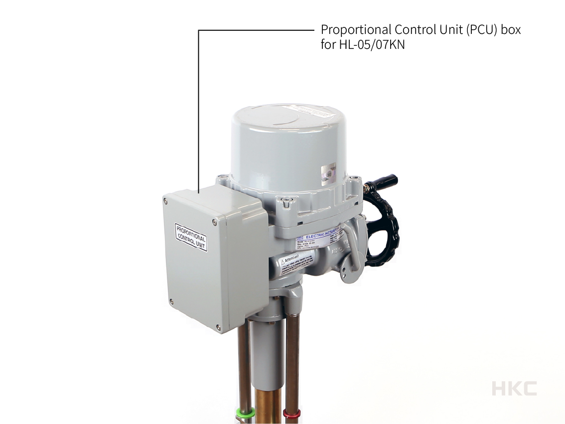
• PCU: Proportional Control Unit (intput/output: 0-10 V dc or 4-20 mA dc)
• PROFIBUS DP interface modules
• MODBUS modules
• CPT: Current Position Transmitter (output: 4-20 mA dc)
• PCU: Proportional Control Unit (intput/output: 0-10 V dc or 4-20 mA dc)
• PROFIBUS DP interface modules
• MODBUS modules
Local control option
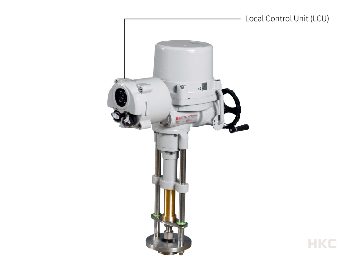
• LCU-B: LED local control unit (integral switch)
• LCU-C: LCD local control unit (integral switch, auto phase discriminator, separate terminal box)
• RBP: Rechargeable Battery Pack for emergency fail safe operation
• LCU-C: LCD local control unit (integral switch, auto phase discriminator, separate terminal box)
• RBP: Rechargeable Battery Pack for emergency fail safe operation
Other
• MSB: Mounting support base & driving rod
Color
 RedRAL 3001
 BlueRAL 5005
 YellowRAL 1033
 Light greyRAL 7035
 Other
 Nano coatingEnhance corrosion resistance
[APPENDIX]
HL Series Coding System
HL – XXkN a b c d e f g (XX : 05,07,10,12,15,18,20,25)
a = Enclosure
1 : Weather proof (IP 67)
2 : Submersible (IP 68, 10m / 72 hr)
3 : Flameproof type (IECEx, ATEX, KCs, EAC, [CCC, CNEX Ex db IIB T4 Gb, IP 67— 25 r0])
[4 : Dust ignition proof (IECEx, ATEX, [CCC, CNEX Ex tb IIIC T135℃ Db, IP67 — 25 r0])
b = Input Voltage
1 : 110 V ac / 1 Ph
2 : 220 V ac / 1 Ph
3 : 220 V ac / 3 Ph
4 : 380 V ac / 3 Ph
5 : 440 V ac / 3 Ph
6 : 460 V ac / 3 Ph (Except HL-05kN, HL-07kN)
[7 : 24 V dc
8 : 24 V ac/dc
9 : 12 V dc
A : 12 V ac/dc ——————————————–19 rev0]
c = Option 1 : Control Unit
0 : Without control unit
1 : ICU (Integral digital Control Unit : LCU C+IMS+Auto Phase Discriminator)
2 : SICU (Semi-Integral Control Unit : LCU B+IMS+Phase Protect Indicator)
3 : RBP (Rechargeable Battery Backup: except explosion proof type)
4 : IMS (Integral Magnetic Starter)
5 : LCU-Z : [except explosion proof type — 21 rev0]
d = Option 2 : Software
0 : [Without software
1 : PIU (Potentiometer Unit : 0~1kΩ)
2 : CPT (Current Position Transmitter : 4~20mA)
3 : PCU (Proportional Control Unit : IN/OUT 0~10V , 4~20mA)
4 : MOB (ModBus Communication protocol)
5 : PRB (ProfiBus Communication protocol) ———————–19 rev0]
e = Option 3 : Additional Switches
0 : Without additional switches
1 : 2ALS (Additional limit switches) [not applied 05kN and 07kN
2 : 2ATS (Additional force switches) [not applied 05kN and 07kN — 25 rev0]
f = Option 4 : MSB
0 : Without MSB
1 : MSB (Mounting support base for valve) ——————– 19 rev0]
g = Option 5 : Fire Proofing Actuator [(except explosion proof type) — 21 rev0]
0 : Without FPA 1 / FPA 2
1 : FPA 1 (Fire Proofing Actuator : 1050 ± 5℃ / 50min)
2 : FPA 2 (Fire Proofing Actuator : 250 ± 5℃ / 150min) — 18 Rev1]
HL – XXkN a b c d e f g (XX : 05,07,10,12,15,18,20,25)
a = Enclosure
1 : Weather proof (IP 67)
2 : Submersible (IP 68, 10m / 72 hr)
3 : Flameproof type (IECEx, ATEX, KCs, EAC, [CCC, CNEX Ex db IIB T4 Gb, IP 67— 25 r0])
[4 : Dust ignition proof (IECEx, ATEX, [CCC, CNEX Ex tb IIIC T135℃ Db, IP67 — 25 r0])
b = Input Voltage
1 : 110 V ac / 1 Ph
2 : 220 V ac / 1 Ph
3 : 220 V ac / 3 Ph
4 : 380 V ac / 3 Ph
5 : 440 V ac / 3 Ph
6 : 460 V ac / 3 Ph (Except HL-05kN, HL-07kN)
[7 : 24 V dc
8 : 24 V ac/dc
9 : 12 V dc
A : 12 V ac/dc ——————————————–19 rev0]
c = Option 1 : Control Unit
0 : Without control unit
1 : ICU (Integral digital Control Unit : LCU C+IMS+Auto Phase Discriminator)
2 : SICU (Semi-Integral Control Unit : LCU B+IMS+Phase Protect Indicator)
3 : RBP (Rechargeable Battery Backup: except explosion proof type)
4 : IMS (Integral Magnetic Starter)
5 : LCU-Z : [except explosion proof type — 21 rev0]
d = Option 2 : Software
0 : [Without software
1 : PIU (Potentiometer Unit : 0~1kΩ)
2 : CPT (Current Position Transmitter : 4~20mA)
3 : PCU (Proportional Control Unit : IN/OUT 0~10V , 4~20mA)
4 : MOB (ModBus Communication protocol)
5 : PRB (ProfiBus Communication protocol) ———————–19 rev0]
e = Option 3 : Additional Switches
0 : Without additional switches
1 : 2ALS (Additional limit switches) [not applied 05kN and 07kN
2 : 2ATS (Additional force switches) [not applied 05kN and 07kN — 25 rev0]
f = Option 4 : MSB
0 : Without MSB
1 : MSB (Mounting support base for valve) ——————– 19 rev0]
g = Option 5 : Fire Proofing Actuator [(except explosion proof type) — 21 rev0]
0 : Without FPA 1 / FPA 2
1 : FPA 1 (Fire Proofing Actuator : 1050 ± 5℃ / 50min)
2 : FPA 2 (Fire Proofing Actuator : 250 ± 5℃ / 150min) — 18 Rev1]


Ulasan
Belum ada ulasan.